

Configuring PoE network devices means enabling simultaneous power and data delivery over standard Ethernet cables through precise settings on switches, injectors, and powered devices (PDs). Power over Ethernet, governed by IEEE standards 802.3af, 802.3at, and 802.3bt, eliminates the need for separate power supplies at every endpoint, from IP cameras to VoIP phones to wireless access points. This guide walks you through the standards you need to know, the tools required before you touch a single port, a step-by-step configuration process for Cisco Catalyst switches and centralized controllers like Versa Networks Director, and a practical troubleshooting framework for power budget failures and device conflicts.
What are the key PoE standards and device types for configuration?
Understanding the three primary IEEE standards is the non-negotiable first step before you configure power over Ethernet on any switch port.
| Standard | Max PSE Output | Wire Pairs Used | Typical Use Case |
|---|---|---|---|
| IEEE 802.3af | 15.4 W | 2 pairs | IP phones, basic cameras |
| IEEE 802.3at (PoE+) | 30 W | 2 pairs | PTZ cameras, dual-band APs |
| IEEE 802.3bt (PoE++) | Up to 100 W | 4 pairs | Video conferencing, thin clients |
The power delivered to the PD is always less than the PSE output due to cable losses: 802.3af delivers roughly 12.95 W at the device, and 802.3at delivers approximately 25.5 W. That gap matters when you are sizing power budgets for high-density deployments.
Every PoE network has two device roles. Power Sourcing Equipment (PSE) is the device that supplies power, either a PoE switch or a midspan injector. The Powered Device (PD) is the endpoint that receives power, such as a Cisco IP phone, Ubiquiti access point, or Axis IP camera. Misidentifying which role a device plays is the most common source of configuration errors.
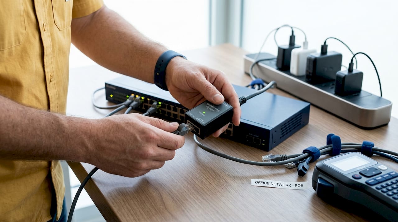
PoE injectors fill a specific gap: they add PoE capability to a standard Ethernet link when your switch lacks native PoE support. A PoE injector connects between the switch port and the PD, passing data through while injecting power onto the cable. They are operationally simple but require careful cabling and documentation to avoid miswiring that mimics network failures.
Compatibility failures most often occur when a passive PoE injector is connected to a device expecting active PoE negotiation. Active PoE uses detection and classification handshakes defined by IEEE; passive PoE applies voltage without negotiation and can damage non-compatible devices. Always verify whether your PD requires active or passive PoE before selecting an injector.
What tools and prerequisites do you need before configuring PoE?
Arriving at the switch console without a completed prerequisites checklist is how configuration sessions turn into multi-hour troubleshooting exercises.
Hardware you need on hand:
- PoE-capable switch (managed switches from Netgear, Cisco, or similar) or a midspan PoE injector
- Cat5e or Cat6 Ethernet cables (Cat6 is preferred for 802.3bt deployments to minimize voltage drop)
- Compatible PDs with confirmed IEEE standard support documented in their datasheets
- A laptop or terminal with console or SSH access to the switch
Software and platform requirements:
- Switch management console or CLI access (Cisco IOS, Netgear ProSAFE, or equivalent)
- Centralized SD-WAN or network controller if applicable (Versa Networks Director supports PoE port priority configuration directly from its interface)
- Current switch firmware, since older firmware versions frequently misclassify PD power classes
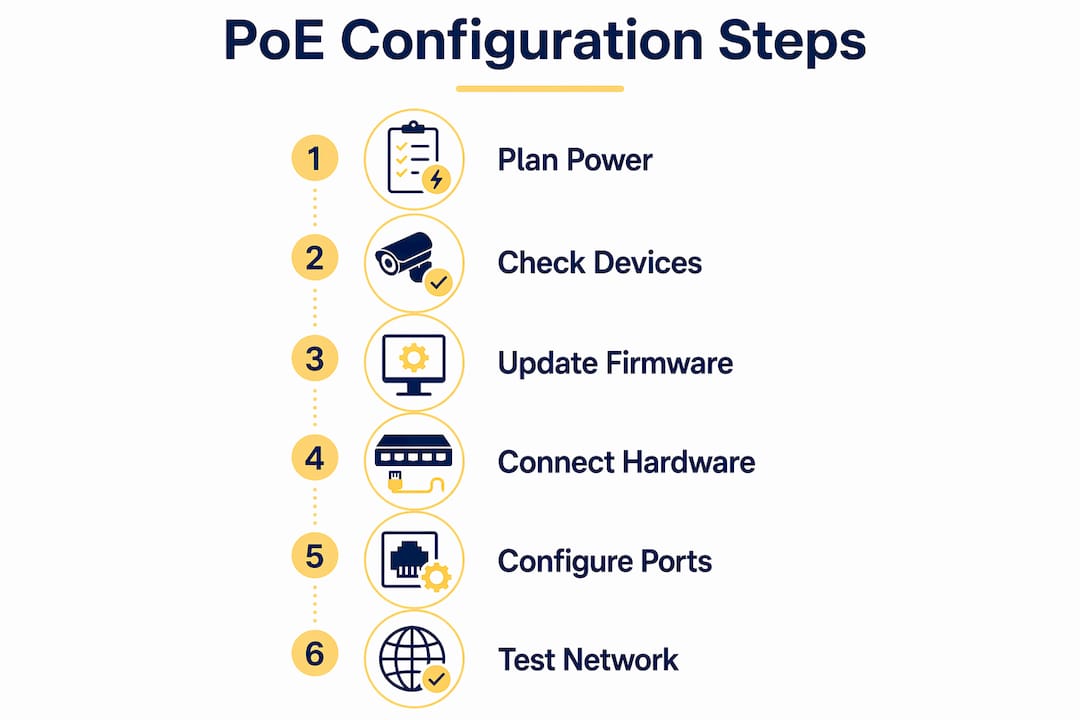
Power budget planning is the prerequisite most administrators skip, and it is the one that causes the most post-deployment failures. Add up the maximum wattage draw of every PD you plan to connect, then compare that total against your switch’s global PoE budget. A 48-port switch rated at 370 W total cannot simultaneously power 48 devices drawing 15.4 W each (that would require 739 W). Map your devices to ports before you configure a single interface.
Pro Tip: Check each PD’s datasheet for its actual power class, not just its maximum draw. A device rated at Class 3 (up to 15.4 W) may only draw 8 W under normal operation. Using real consumption figures rather than maximums lets you fit more devices within your global budget without sacrificing reliability.
Firmware updates deserve a dedicated step in your checklist. Cisco Catalyst switches and Netgear managed switches both release firmware updates that address PoE classification bugs. A switch running outdated firmware may assign the wrong power class to a PD, either starving it of power or over-allocating from the global budget.
How to configure PoE switches and devices step by step
Follow this sequence on a Cisco Catalyst 9200 series switch. The same logical flow applies to Netgear managed switches and Versa Networks SD-WAN controllers, though command syntax differs.
-
Access the switch CLI. Connect via SSH or console cable and enter privileged EXEC mode with "enable`.
-
Verify the global PoE budget. Run
show power inlineto display total available wattage, allocated wattage, and remaining capacity. This is your baseline before any port configuration. -
Enter interface configuration mode. Use
interface GigabitEthernet1/0/1(substitute your target port) to scope your changes to a specific port. -
Set the PoE power mode. The
power inline autocommand tells the switch to detect and power any compliant PD. Usepower inline neverto disable PoE on ports where no PD is connected, which prevents accidental power delivery to non-PoE devices. -
Cap per-port wattage. The Cisco Catalyst 9200 supports per-port wattage caps using
power inline wattage max [value]. Setting a cap below the device’s maximum class prevents a single PD from consuming disproportionate budget. -
Assign port priority. Use
power inline port priority {low | high | critical}to define which ports retain power when the global budget is exhausted. Assigncriticalto security cameras and core access points. Assignlowto non-essential endpoints like digital signage. -
Configure PoE startup delays where needed. Campus switch PoE configurations support
poe-delaycommands to stagger device power-on sequences, preventing inrush current spikes that can trip the global budget at boot time. -
Verify power allocation. Return to
show power inlineand confirm each port shows the correct allocated wattage and PD class. A port showing “off” for a connected PD indicates a classification failure or budget exhaustion. -
Enable legacy device detection if needed. Enabling compatibility detection allows the switch to power PDs that do not fully comply with IEEE 802.3af or 802.3at, which is critical for older IP cameras or third-party devices.
For injector-based setups, connect the injector’s data input port to your switch, then run the PoE output port to your PD. Verify the injector’s LED indicators confirm power delivery before assuming the PD is receiving power.
Pro Tip: Use static power allocation on ports connected to critical infrastructure. Static mode allocates the configured wattage regardless of what the PD negotiates, giving you predictable budget consumption and eliminating the timing-related power failures that occur when dynamic allocation races against device boot sequences.
How to manage and troubleshoot common PoE configuration issues
Most PoE failures fall into four categories: budget exhaustion, wattage mismatches, priority misconfiguration, and cable-related voltage drop.
Budget exhaustion occurs when the sum of allocated port wattages exceeds the switch’s global PoE budget. The switch powers off the lowest-priority ports first. Versa Networks’ controller follows the same logic: higher-priority ports retain power, and ties are broken by port number order. If you have not mapped physical ports to logical priorities, you will not know which device just lost power during a budget event.
Wattage mismatches are the leading cause of individual port failures. Active PoE uses detection and classification; passive PoE does not. Connecting a passive injector to a device expecting active negotiation either fails to power the device or, in worst cases, damages it. Always confirm the injector type matches the PD’s requirements.
Priority misconfiguration creates power-off cascades that are genuinely difficult to diagnose. Incorrect port priority mapping means the switch powers off a device you considered critical because its port was assigned low priority. Maintain a physical-to-logical port map and review it every time you add a device to the network.
Cable quality and length affect power delivery more than most administrators expect. The 100-meter Ethernet limit applies to power delivery as well as data. Long cable runs on thin-gauge wire increase resistance and voltage drop, which can cause a PD to receive insufficient voltage even when the switch reports full wattage allocation.
When a device appears powered off despite the switch showing allocated wattage on that port, check the PD’s LED indicators first, then measure cable length and inspect for damaged connectors. If the port shows power allocated but the device is unresponsive, run
poe reinitializeon the Cisco Catalyst platform to reset the port without a full device reboot.
CDP (Cisco Discovery Protocol) and LLDP (Link Layer Discovery Protocol) are your best monitoring tools for ongoing power negotiation visibility. Both protocols report the power class and actual consumption of connected PDs, letting you catch devices that are drawing more than their classified wattage before a budget event occurs.
Key takeaways
Successful PoE network configuration requires mapping device power classes to switch capabilities before touching a single port, then enforcing wattage caps and priority assignments to prevent budget failures.
| Point | Details |
|---|---|
| Know your PoE standard | Match IEEE 802.3af, 802.3at, or 802.3bt to each PD’s datasheet before configuring any port. |
| Plan the power budget first | Sum all PD wattage requirements and compare against the switch’s global PoE budget before deployment. |
| Assign port priorities deliberately | Mark cameras and core APs as critical so they retain power during budget exhaustion events. |
| Use wattage caps per port | Per-port caps on Cisco Catalyst 9200 switches prevent single devices from consuming disproportionate budget. |
| Monitor with CDP and LLDP | These protocols surface real-time PD power consumption, catching overdraws before they cause outages. |
What I’ve learned configuring PoE networks in the field
The configuration step that consistently causes the most post-deployment grief is not the CLI work. It is the failure to document physical-to-logical port mappings before assigning priorities. I have seen network teams spend hours diagnosing a “random” power outage only to discover that their most critical access point was on a low-priority port because someone assumed port numbering matched physical labeling on the patch panel. It never does.
My recommendation: before you run a single power inline command, print your switch’s port layout, physically label every cable at both ends, and record which PD connects to which logical port number. That 20-minute exercise prevents hours of incident triage.
On the standards side, I have watched teams deploy 802.3at switches and then connect 802.3bt devices expecting full power delivery. The PoE standard mismatch is a root cause that is embarrassingly easy to miss when procurement and network teams are not communicating. If you are deploying video conferencing endpoints or high-wattage thin clients, verify your switch supports 802.3bt before the hardware arrives on site.
For legacy environments where replacing switches is not feasible, midspan injectors are genuinely effective. The key discipline is cabling documentation. An undocumented injector in a rack looks identical to a patch panel coupler, and the next administrator will spend real time figuring out why a port “has no PoE” when the switch is not even the power source.
Finally, if your budget allows, invest in a managed PoE switch with per-port power monitoring dashboards. The visibility alone pays for itself the first time you catch a device drawing 28 W on a port you configured for 15 W.
— James
Upgrade your PoE network with the right hardware
Atticusgoods carries a curated selection of managed PoE switches built for the configuration workflows described in this guide. The Netgear GS348PP delivers advanced PoE+ power management with per-port controls that align directly with the priority and wattage cap strategies covered above. For deployments requiring high-density port counts and fiber uplinks, the Netgear Gigabit PoE+ Smart Switch with dedicated 10G SFP+ ports handles demanding enterprise environments. Atticusgoods ships next day across the United States, so your hardware arrives before your configuration window closes. Browse the full networking catalog at Atticusgoods to find the right switch for your deployment.
FAQ
What is the difference between 802.3af and 802.3at PoE?
IEEE 802.3af delivers up to 15.4 W per port at the PSE, while 802.3at (PoE+) delivers up to 30 W, both using two wire pairs. Choose 802.3at for devices like PTZ cameras or dual-band access points that exceed 15 W draw.
How do I check if my switch has enough PoE budget?
Run show power inline on Cisco Catalyst switches to display total available wattage, currently allocated wattage, and remaining capacity. Compare the remaining capacity against the sum of your planned PD power requirements before connecting new devices.
What causes a PoE port to show allocated power but the device stays off?
The most common causes are cable voltage drop from excessive length or poor-quality connectors, a wattage mismatch between the PD’s class and the port cap, or a passive versus active PoE conflict. Run poe reinitialize on Cisco platforms to reset the port without rebooting the switch.
When should I use a PoE injector instead of a PoE switch?
Use a PoE injector when your existing switch lacks native PoE support and replacing it is not feasible. Connect the injector between the switch port and the PD, verify power delivery via LED indicators, and maintain clear cabling documentation to avoid miswiring issues.
How does port priority affect PoE device availability?
When a switch’s global PoE budget is exhausted, it powers off the lowest-priority ports first. Ports assigned critical priority retain power last, making priority assignment the single most important configuration decision for network availability during power shortage events.
Recommended
- Netgear Gigabit PoE+ Smart Switches | Remote Management – Atticus Goods
- Netgear Gigabit PoE+ Smart Switches with 4 Dedicated 10G SFP+ Ports - – Atticus Goods
- Netgear M4250-40G8F-PoE+ AV Line Managed Switch - Atticus Goods
- Netgear AV Line M4250-10G2F-PoE+ 8x1G PoE+ 125W 2x1G and 2xSFP Managed – Atticus Goods