

Marine wiring is the practice of using stranded, tinned copper conductors sized and protected per ABYC E-11 standards to safely power boat electrical systems in corrosive, high-vibration environments. Unlike household or automotive wiring, marine electrical wiring must resist salt air, constant moisture, and the relentless vibration of a running engine. Get it wrong and you face dim navigation lights, fried electronics, or worse, an electrical fire below deck. This guide covers everything from wire selection and sizing to overcurrent protection placement and DC panel wiring, giving you the knowledge to build or inspect a safe, reliable boat electrical system.
What makes marine wiring different from other wiring?
Marine wiring operates in conditions that would destroy standard automotive or household wire within a season. Marine-grade wire must be stranded, tinned copper rated to UL 1426 to resist corrosion in salt and moisture environments. The tinning process coats each copper strand with a thin layer of solder alloy, blocking oxidation that would otherwise eat through bare copper connections within months. Stranded construction distributes flex stress across dozens of individual strands, preventing the vibration fractures that crack solid conductors.
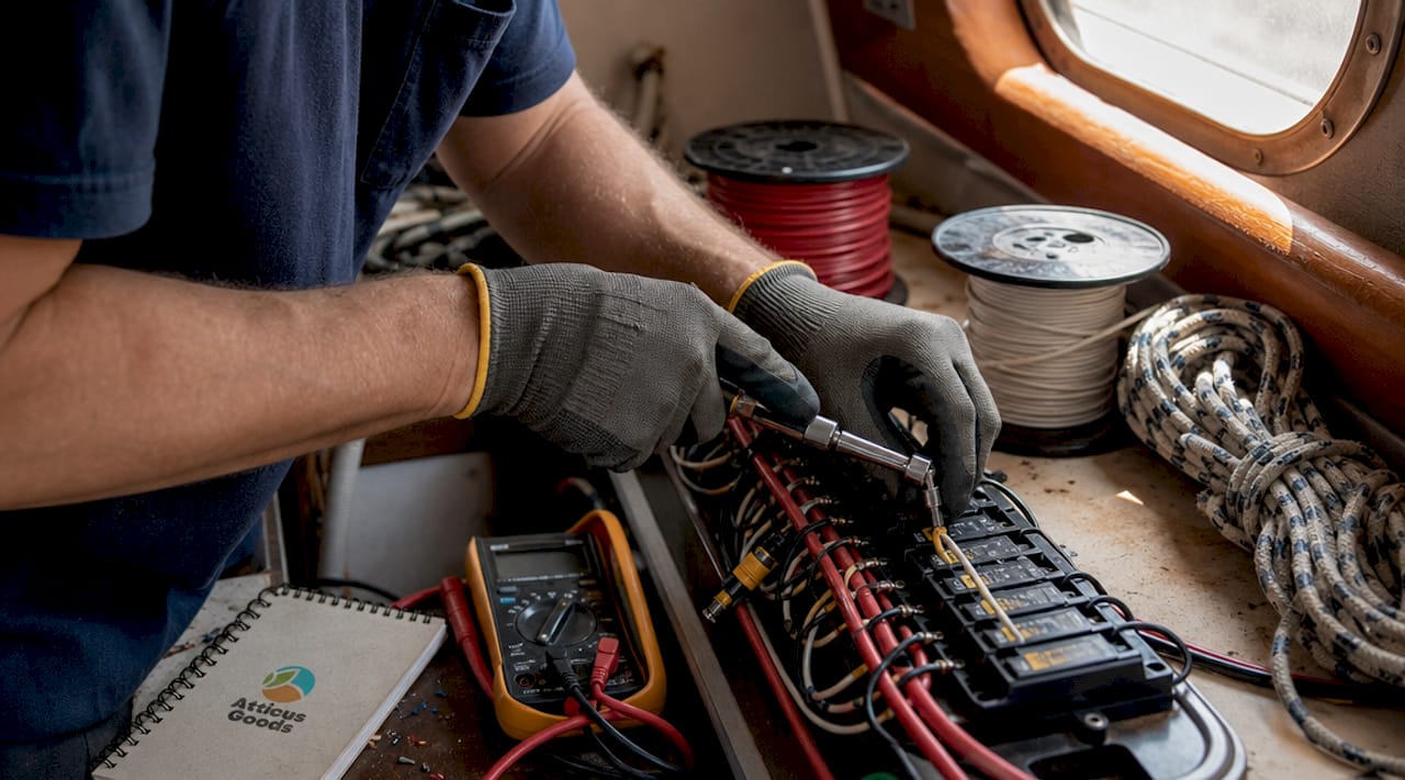
The governing standard for all of this is ABYC E-11, published by the American Boat and Yacht Council. ABYC E-11 sets specific requirements for conductor construction, insulation ratings, voltage drop limits, overcurrent protection placement, and color coding. Solid conductors are prohibited outright under ABYC E-11 because vibration from engines and hull flex causes them to fracture inside the insulation, creating invisible failure points.
Common marine wire types include primary wire (single conductor, used for most DC runs), duplex cable (two conductors in one jacket for positive and negative together), and triplex cable (three conductors, common for bilge pump circuits). Insulation must be fire-retardant and rated for the environment, with UL 1426 being the accepted standard for boat wiring.
- Tinned stranded copper: Required for all conductors; resists corrosion and vibration fatigue
- UL 1426 insulation: Fire-retardant, moisture-resistant, and rated for marine environments
- No solid conductors: ABYC E-11 prohibits them due to vibration fracture risk
- Primary, duplex, and triplex cable: Each serves specific circuit types aboard
Pro Tip: When buying marine wire, check for the UL 1426 marking printed on the insulation jacket itself. If it is not there, the wire is not truly marine-rated, regardless of what the packaging claims.
How do you size wire for a marine electrical circuit?
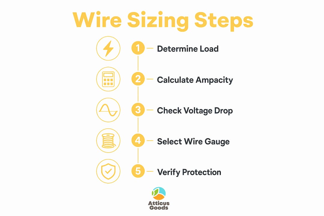
Wire sizing is where most DIY marine electrical wiring projects go wrong. Wire sizing must account for both ampacity and voltage drop over the full round-trip length of conductors, and ABYC E-11 requires you to use whichever calculation produces the larger wire gauge.
Ampacity is the maximum current a wire can carry without overheating. Voltage drop is the loss of voltage along the wire run due to resistance. Marine wiring targets voltage drop limits of 3% for critical circuits and 10% for non-critical, which translates to 0.36V and 1.2V respectively on a 12V system. A navigation light circuit running at 10 amps over a 20-foot one-way run actually requires a 40-foot round-trip calculation. Using only the one-way distance is the single most common sizing error, and it produces wire that runs warm and delivers inadequate voltage to the load.
Here is a simplified reference for common 12V DC circuits using a 3% voltage drop limit:
| Circuit load (amps) | Round-trip length (ft) | Minimum AWG |
|---|---|---|
| 10 | 20 | 14 AWG |
| 15 | 20 | 12 AWG |
| 20 | 30 | 10 AWG |
| 30 | 40 | 8 AWG |
| 50 | 20 | 6 AWG |
Always derate wire ampacity when conductors are bundled together in a harness or run through a hot engine compartment. Bundling three or more wires together reduces each wire’s ability to shed heat, which means you may need to step up one gauge size beyond what the table suggests.
- Calculate the total current draw of the circuit in amps
- Measure the full round-trip wire length (positive run plus negative return)
- Look up the required gauge for ampacity from an ABYC ampacity table
- Calculate voltage drop using the round-trip length and select the gauge that keeps drop within 3% or 10%
- Use the larger of the two gauge results
Pro Tip: Marine electricians treat voltage drop as a performance and equipment protection issue, not just a safety criterion. Undersized wire to a windlass or electric winch causes motor overload and premature failure, not just slow operation.
Where do overcurrent protection devices go in a boat’s wiring?
Overcurrent protection placement is the most safety-critical aspect of marine electrical wiring, and it is also the most commonly violated rule on older boats. Every ungrounded positive conductor must have overcurrent protection within 7 inches of the battery or bus, or within 72 inches if the wire is protected by a sheath, conduit, or enclosure along its entire length. The purpose is to protect the wire itself, not just the load at the end of the circuit.
ABYC E-11 stresses that overcurrent devices must be placed close to power sources to prevent unprotected wire segments from becoming fire hazards in a fault condition. An unprotected wire run from a battery to a panel can carry hundreds of amps during a short circuit, generating enough heat to ignite surrounding materials before any downstream fuse reacts.
A Class T fuse block mounted directly at the battery positive terminal is the accepted solution for protecting the main feed cable. Class T fuses have the high Adequate Interrupting Capacity ratings required to safely clear the fault currents that large lithium or AGM battery banks can deliver.
Overcurrent devices must be coordinated so the one closest to a fault clears first, which means downstream branch fuses must be rated lower than the upstream main fuse. Neglecting this coordination means a fault on a branch circuit could blow the main fuse instead, cutting power to the entire boat rather than just the affected circuit.
- Main feed: Class T fuse or ANL fuse block within 7 inches of battery positive terminal
- Branch circuits: Individual breakers or fuses sized to the wire gauge, not just the load
- Fuse ratings: Must not exceed the ampacity of the wire being protected
- AIC ratings: Fuses must have adequate interrupting capacity for the battery bank in use
- No shared protection: Each circuit gets its own dedicated overcurrent device
Best practices for marine wiring installation and maintenance
The quality of a marine wiring installation comes down to terminations and support. Terminations are the most common failure point in boat electrical systems. Even the best marine-grade wire fails if connections are poorly made or left unsealed against moisture and vibration. ABYC requires marine-grade crimp terminals and adhesive-lined heat-shrink tubing. Wire nuts and standard automotive push-on connectors are prohibited.
Adhesive-lined heat-shrink ring terminals create a watertight mechanical bond that resists both moisture intrusion and pull-out force. A proper marine crimp tool applies the correct die geometry to deform the barrel around the wire strands without cutting them. Using a hardware store crimper on marine terminals produces connections that look fine but fail within a year of exposure to bilge humidity.
Marine electrical failure often results from corrosion beneath insulation and brittle terminations, which is why re-termination rather than patching is the recommended approach when rewiring degraded runs. On boats older than 15 years, plan to replace every terminal on any circuit you touch. The wire itself may look fine while the connection beneath the insulation is green with oxide.
- Support wire runs every 18 inches using nylon clamps or cable ties with mounting bases
- Use grommets at every bulkhead pass-through to prevent chafe on sharp edges
- Route positive and negative conductors together to minimize electromagnetic interference
- Keep wiring above the waterline wherever possible; bilge runs require protective conduit
- Follow ABYC color coding: yellow for DC negative, red for DC positive, and specific colors for engine and navigation circuits
- Inspect annually for cracked insulation, green terminals, and loose connections
Pro Tip: When rewiring an older boat, photograph every existing connection before you remove anything. Older boats often have undocumented circuits, and a photo record saves hours of tracing later.
How do you wire a marine DC distribution panel?
A properly wired marine DC distribution panel is the organizational center of your boat electrical system. A correctly wired panel uses a fused main feed into the panel, individually protected branch circuits, and a common negative return bus for reliable fault isolation. This topology keeps all switched and fused positives centralized while returns flow back to a single bus, eliminating ground loops that cause corrosion and instrumentation errors.
- Calculate total load by adding the amperage of every circuit the panel will serve, then add 20% margin for future circuits
- Size the main feed cable from the battery to the panel using the total load and round-trip length
- Install a Class T fuse block at the battery positive terminal, sized to the main feed cable ampacity
- Connect the main feed to the panel’s positive bus bar
- Wire each branch circuit from its breaker to the load, sizing each conductor individually
- Return all negative conductors to the panel’s common negative bus bar
- Run a single negative cable from the bus bar back to the battery negative terminal
- Test each circuit with a multimeter and document the voltage drop at full load
Choosing the right panel matters. Blue Sea Systems and Paneltronics both manufacture ABYC-compliant panels with pre-labeled breaker positions, integrated bus bars, and clear acrylic covers. A panel with 12 breaker positions gives most trailerable boats room to grow without rewiring the distribution center.
| Panel feature | Why it matters |
|---|---|
| Individual circuit breakers | Allows fault isolation without cutting power to the whole boat |
| Common negative bus bar | Eliminates ground loops and simplifies returns |
| Labeled breaker positions | Speeds troubleshooting and satisfies ABYC documentation requirements |
| Waterproof cover | Protects breakers from spray in open cockpit installations |
Key takeaways
Safe, reliable marine wiring requires tinned stranded copper wire sized for both ampacity and voltage drop, overcurrent protection placed within 7 inches of the battery source, and adhesive-lined heat-shrink terminations at every connection.
| Point | Details |
|---|---|
| Use marine-rated wire | Tinned stranded copper rated to UL 1426 is the only wire type that survives marine environments long-term. |
| Size for voltage drop first | Calculate round-trip length and keep drop to 3% on critical circuits to protect motors and electronics. |
| Protect the main feed | A Class T fuse block at the battery terminal is required; branch fuses cannot protect the main cable. |
| Seal every termination | Adhesive-lined heat-shrink terminals prevent the moisture intrusion that causes most marine wiring failures. |
| Document your panel | Label every breaker and record voltage drop at full load to simplify future troubleshooting. |
What I have learned from rewiring boats the hard way
The first time I pulled apart the wiring on a 1988 sportfisher, I found bare copper wire twisted together with electrical tape and shoved into a bilge corner. The tape had turned to mush. The copper was black. The boat had been running like that for years, which tells you something about how much abuse a boat can absorb before it finally fails catastrophically.
What that project taught me is that the ABYC standards are not bureaucratic overhead. They are a distillation of what actually goes wrong on boats. The 7-inch rule for fuse placement exists because someone’s boat burned. The prohibition on wire nuts exists because someone lost electronics to a corroded twist connection. Every rule has a story behind it.
The mistake I see most often on DIY installs is skipping the main feed fuse because the installer figures the branch fuses will handle any fault. The main battery feed requires its own overcurrent protection because branch fuses are sized to protect their own conductors, not the heavy cable running from the battery to the panel. That cable can carry 200 amps or more in a dead short, and a 20-amp branch fuse will not even flinch.
My practical advice: buy better wire than you think you need, use a proper ratcheting marine crimp tool, and never patch a corroded termination. Cut it out and start fresh. The extra hour you spend doing it right is nothing compared to diagnosing a ghost fault at anchor three miles offshore.
— Matthew Vista
Get the right marine wiring supplies from Atticus Goods
Building a safe, ABYC-compliant boat electrical system starts with sourcing the right components. Atticus Goods carries a broad selection of marine electrical supplies including tinned marine-grade wire, Class T fuse blocks, circuit breakers, adhesive-lined heat-shrink terminals, and marine-rated crimp tools. Every product ships next-day across the United States, so you are not waiting a week to finish a project that has your boat out of commission. Whether you are wiring a new panel from scratch or re-terminating an aging system, Atticus Goods stocks the certified components that meet ABYC standards and hold up in real marine conditions.
FAQ
What type of wire is required for marine wiring?
Marine wiring requires stranded, tinned copper wire rated to UL 1426. Solid conductors and bare copper wire are prohibited under ABYC E-11 because they fail from vibration and corrosion in marine environments.
What is the voltage drop limit for marine circuits?
ABYC E-11 sets a 3% voltage drop limit for critical circuits and 10% for non-critical circuits on 12V systems. Always calculate voltage drop using the full round-trip wire length, not just the one-way run.
How close to the battery must a fuse be placed?
Overcurrent protection must be within 7 inches of the battery terminal or bus bar. The limit extends to 72 inches only if the wire is fully protected by a conduit, sheath, or enclosure along its entire length.
Can I use automotive wire on my boat?
Automotive wire is not acceptable for marine use. It uses bare copper strands and insulation that degrades rapidly in salt air and bilge humidity. Only UL 1426-rated tinned stranded copper wire meets ABYC E-11 requirements.
How often should I inspect my boat’s wiring?
Inspect all visible wiring, terminals, and connections at least once per season. Pay particular attention to connections in bilge areas and engine compartments, where heat and moisture accelerate corrosion beneath insulation.